QVF® Glass Equipment
We are the largest supplier of equipment made of highly corrosion resistant borosilicate glass 3.3 for the chemical and pharmaceutical industries. With our QVF® SUPRA-Line, we are the sole manufacturer of glass components with a nominal size of up to DN1000. These QVF® components are designed and manufactured to the highest quality standards for more than sixty years at our facilities in Germany.
- The raw material we use is DURAN® borosilicate glass 3.3 according to ASTM E438 TYPE I and DIN ISO 3585, which exceeds EN 1595 by far, and ensures due to the unique production processes secure and reliable wall thicknesses.
- We design, manufacture and calculate our glass components according to EN 1595 and AD 2000.
- Our experienced glass engineers, state-of-the-art equipment, and manufacturing processes developed in-house ensure high levels of dimensional accuracy in the most complex of components.
- Our manufacturing process is certified according to DIN ISO 9001.
- Our products are CE-marked in accordance with Pressure Equipment Directive 97/23/EC and 2014/68/EU (module H1).
- The production number on each component ensures manufacturing traceability.
- Each component bears an unique article number for identification.
- The QVF® logo assures quality in all of our glass components.
Additional safety can be optionally provided by the QVF®SECTRANS coating to protect the surface from external damage, as e.g. scratches. As this patented coating is electrically conductive any eventual electrostatic charges are avoided so that ATEX compliant glass equipment for hazardous areas classified as Zone 0IIC can be provided. Supplying glass systems over decades to the chemical and pharmaceutical industries you can rely on our engineering competence in the design and manufacture of key components for the construction of corrosion resistant plants.
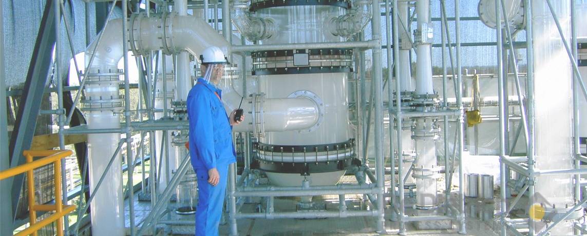
Manufacturing of a QVF® glass column DN1000

50l Universal reactor


